
I describe about “Netlist” that is necessary for using SPICE here.
SPICE is a software for simulating the circuits. To simulate the circtis using SPICE, we need to teach the information of the original circuits to SPICE. It is Netlists.
Netlist is the file expressing the connection of the circit elements. SPICE loads netlist, and makes the circuit equation from netlist. After that, SPICE simulates the original circuit by solving the circuit equation using numerical method.
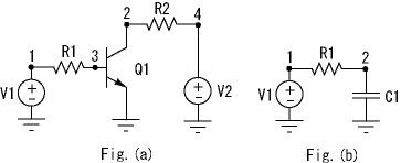
Hence, we make the netlist to use SPICE. In here, I explain how to describe netlist. We consider the circuit shown in Fig.(a). the value of elements are V1=5V, V2=12V, R1=100, R2=300, respectively. This circuit is nonlinear circuit consisting of two independent voltage sources, two resistors and one transistor. I use this circuit to explain ablut netlist.
If we want to simulate this circuit in SPICE, we make the netlist as follows.
*** EX1 ***
V1 1 0 5V
V2 4 0 12V
R1 1 3 100
R2 2 4 300
Q1 2 3 0 N
.MODEL N NPN()
.OP
.END
- Netlist have a set of principles. The fist line of netlist is certainly comment. Hnece, if you write something element, SPICE makes out it. So please be careful.
- Netlist must write .END command in the end line of it.
- The number of erath ground of the circuit is expressed “0”.
- The element of a kind must be assigned the diffrent name. For example, if you use three resistors “R”, the resistors are described R1, R2, R3, respectively.
Well, let’s show the above netlist.
The first line is the comment. “V1” of the second line expresses the independent voltage source. In this description, the independent voltage source V1 is connected from node 1 to datum node. Furthermore, the end of “5” implies that the value of the independent voltage sourceis 5 volts. Hence, the third line implies that the value of the independent voltage source V2 is connected from node 4 to datum node. “R1” of the fourth line expresses the resistor. This description implies that the resistor R1 (100 ohm) is connected from node 1 to datum node. The fifth line implies that the resistor R2 (300 ohm) is connected from node 2 to node 3. “Q1” of the sixth line expresses the transistor. The nodes of the transistor Q are described the base, emitter, corector starting from the left. The end of “N” is the name of transistor, and optional. Hence, in this description, Q1 is connected node 2, 3, 0. The node 2, 3, 0 expresses the base, emmiter, corector, respectively. “.MODEL” expresses the model parameter of the transistor. If you describe nothing in (), then SPICE will use the default value. “.OP” is command to do the DC operating analysis. “.END” implies the end of netlist.
When we simulate the netlist on SPICE, we can obtain the result as follows.
Circuit: *** EX1 ***
Spice 1 -> run
Spice 2 -> print all
v(1) = 5.000000e+000
v(2) = 2.843206e-002
v(3) = 8.979369e-001
v(4) = 1.200000e+001
v1#branch = -4.10206e-002
v2#branch = -3.99052e-002
Note that v1#branch and v2#branch are the currents of independet voltage sources, respectively.
Next, we consider the RC circuit shown in Fig.(b). The netlist of this circuit is shown as follows.
*** EX2 ***
V1 1 0 1V
R1 1 2 1
C1 2 0 1
.IC V(1)=1
.IC V(2)=0
.TRAN 0.1 20 0 0.5
.END
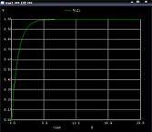
The new descriptions in this netlist are from the fourth line to the seventh line. “C1” of the fourth line is condenser. This description implies that the condenser C1 (1F) is connected from node 2 to datum node. The fifth and sixth line are the initial values of transient analysis. “.TRAN” implies to do the transient analysis. The first number “0.1” of the seventh line implies the increment of display or graphics. The second number “20” implies the termination time of transient analysis. The third number implies starting time of transient analysis. The fourth number “0.5” implies the step size of transient analysis. When we simulate the netlist on SPICE, we can obtain the result as follows.
If you think that you want to learn about the details of netlist, please read the SPICE manual or related references.
References
- L.W. Nagel and D.O. Pederson, “SPICE—Simulation program with integrated circuit emphasis,” Univ. California, Berkeley, CA, April 1973.
- L.W. Nagel, “SPICE2: A computer program to simulate semiconductor circuits,” Univ. California, Berkeley, CA, May 1975.
- A. Vladimirescu, The SPICE Book, John Wiley \& Sons, New York, 1994.
- 浅井秀樹, 渡辺貴之, 電子回路シミュレーション技法, 科学技術出版, 東京, 2003.
- 三浦道子, 名野隆夫, 回路シミュレ-ション技術とMOSFETモデリング, サイペック, 東京, 2003.
- 新原 盛太郎, SPICEとデバイス・モデル—IC設計者に必須のバイポーラ・トランジスタの基礎知識, CQ出版社, 東京, 2005.
- 牛田明夫,田中衛, 電子回路シミュレーション,コロナ社, 東京, 2002.